


What Is a Pipe Jacking Machine and What Does It Do?
A pipe jacking machine is a piece of specialist trenchless construction equipment used to install underground pipelines, culverts, and utility conduits without the need to dig open trenches along the entire route. The machine works by simultaneously cutting through the ground at the front of the bore while hydraulic jacks push pre-formed pipe sections forward from a launch shaft at the rear. As each new pipe section is pushed into the ground, another section is added behind it, building the pipeline progressively through the soil until it exits at a reception shaft on the other side.
Also commonly referred to as a pipe jacking unit, microtunnelling machine, or pipe-pushing machine depending on the pipe diameter and level of automation involved, this equipment is the go-to solution for crossing roads, railways, rivers, airports, and built-up urban areas where open-cut excavation would cause unacceptable disruption, cost, or risk. Pipe jacking machines can install pipes ranging from small-diameter microtunnels of around 250mm right up to man-entry tunnels exceeding 3,000mm in diameter.
The technique was first developed in Japan and Germany in the 1960s and has since become a globally used method in civil engineering, drainage, water supply, gas distribution, and telecommunications infrastructure projects. Today's pipe jacking systems are highly sophisticated, featuring remote-controlled cutting heads, laser guidance systems, slurry circulation for spoil removal, and real-time monitoring of line, grade, and jacking forces.
How a Pipe Jacking Machine Works: The Core Process
Understanding the operational sequence of a pipe jacking operation helps clarify why the method is so effective and what makes each component of the system essential. While individual machine designs vary, the fundamental process follows a consistent sequence across all pipe jacking projects.
Launch and Reception Shaft Construction
Before any pipe jacking can begin, two shafts must be excavated — a launch shaft where the machine starts its bore, and a reception shaft where the machine exits and is retrieved. The launch shaft houses the main hydraulic jacking frame, which provides the thrust force to push the pipe string forward. Shaft dimensions depend on the pipe diameter, pipe section length, and the jacking frame size, but a typical launch shaft for a 1,200mm diameter operation might measure 6–8 metres long and 4–5 metres wide. Both shafts are usually supported with sheet piling, secant pile walls, or precast concrete rings to prevent collapse.
Machine Setup and Alignment
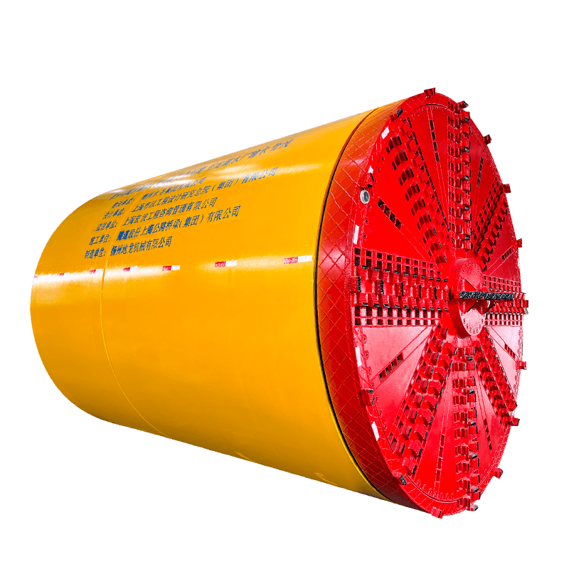
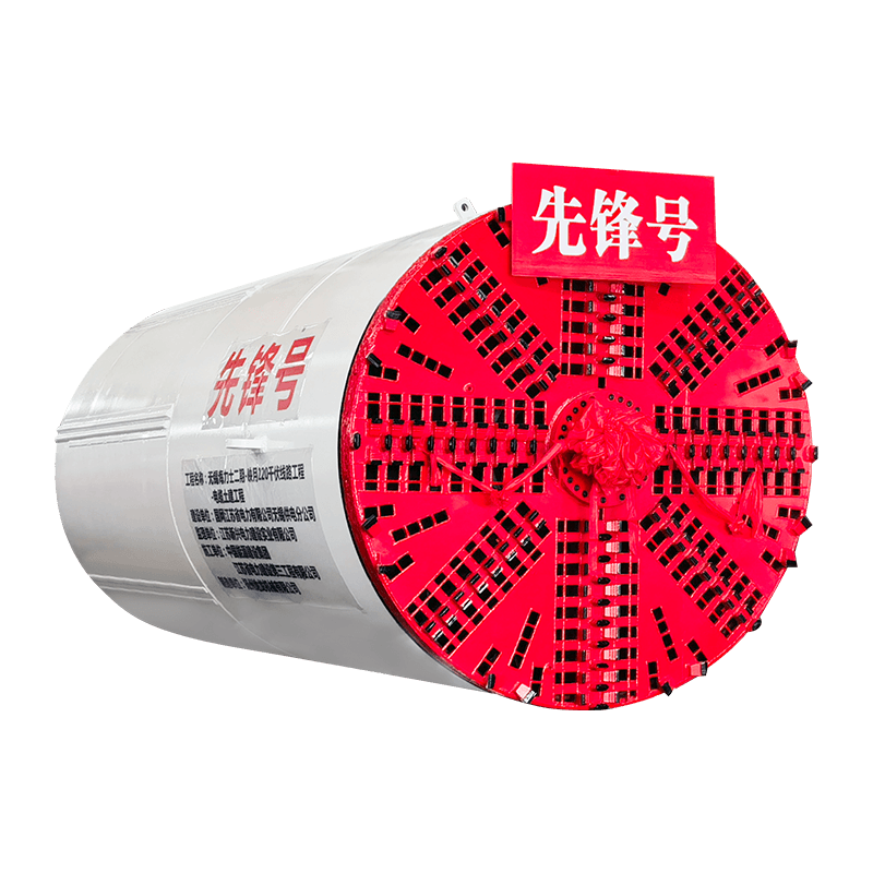
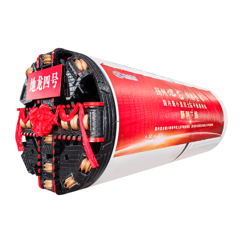
Once the launch shaft is ready, the jacking frame is installed and precisely levelled. A laser theodolite is set up at the rear of the shaft to project a reference beam along the exact design line and gradient of the pipeline. The pipe jacking machine — typically a rotating cutting head mounted on a steerable shield — is positioned on the jacking frame, aligned with the laser, and pushed through the shaft wall into the surrounding ground to begin the bore.
Cutting and Spoil Removal
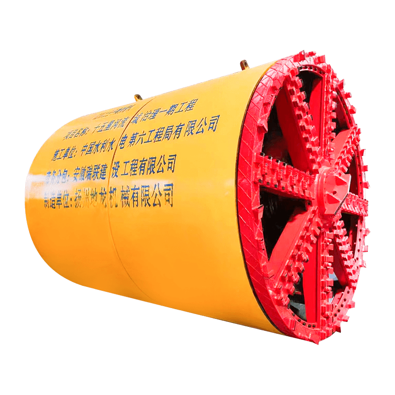
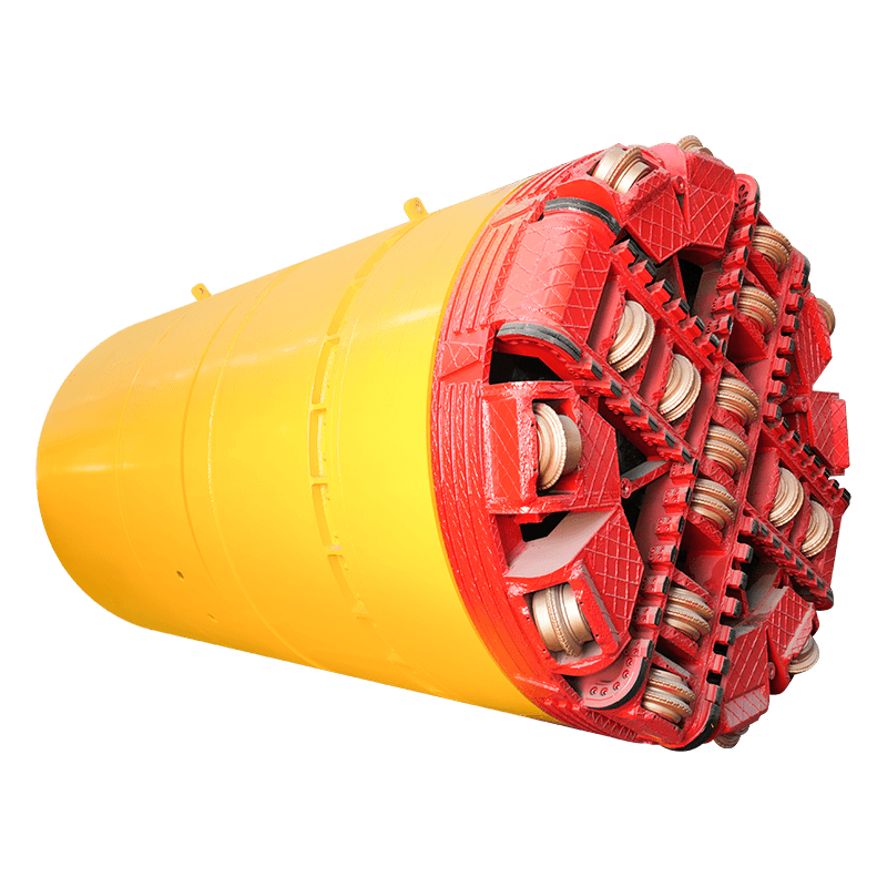
The cutting head rotates continuously, breaking up the ground ahead of the machine. Depending on the soil type, the cutting head may be fitted with drag picks for soft soils, disc cutters for mixed ground, or hardened bits for rock. Excavated spoil is removed from the face through one of two main methods: slurry systems, which use a pressurised bentonite or water slurry to flush cuttings back through a pipe circuit to a surface separation plant; or auger systems, which use a rotating screw conveyor to carry spoil back through the bore to the launch shaft for removal.
Pipe Advancement and Steering
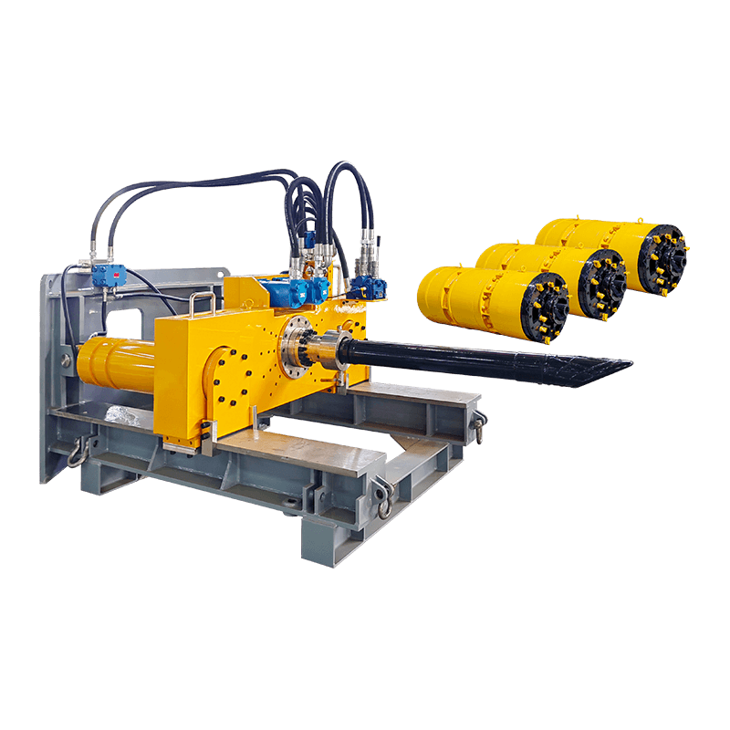
As the cutting head advances, the main jacking rams at the rear of the shaft push the entire pipe string — machine plus all installed pipe sections — forward by one pipe length, typically 1,000mm to 2,500mm per cycle. Once a full pipe section has been pushed into the ground, the jacking rams retract, a new concrete or glass-reinforced pipe (GRP) section is lowered into the shaft and positioned on the frame, and the cycle repeats. Steering corrections are made by adjusting the attitude of the front shield using internal hydraulic steering cylinders, guided by real-time feedback from the laser guidance or gyroscopic navigation system.
Lubrication and Intermediate Jacking Stations
On longer drives, friction between the outer surface of the pipe and the surrounding soil can build up to levels that exceed the capacity of the main jacking frame. To manage this, bentonite or polymer lubricant is injected through ports in the pipe wall at regular intervals to form a slick annular layer around the pipe exterior, dramatically reducing skin friction. For very long drives — typically over 100–150 metres for medium-diameter pipes — intermediate jacking stations (IJS), which are hydraulic rams installed at intervals within the pipe string itself, are used to share the total jacking load across multiple thrust points.
Main Types of Pipe Jacking Machines
The term "pipe jacking machine" covers a broad family of equipment. The correct machine type for a project depends primarily on the pipe diameter, soil conditions, groundwater level, accuracy requirements, and available budget.
| Machine Type | Pipe Diameter Range | Entry Method | Best Suited Soil |
| Slurry Microtunnelling Machine | 250mm – 1,500mm | Remote-controlled (no man-entry) | Soft to hard soils, below water table |
| Auger Boring Machine (ABM) | 300mm – 1,200mm | Remote-controlled | Dry, cohesive soils above water table |
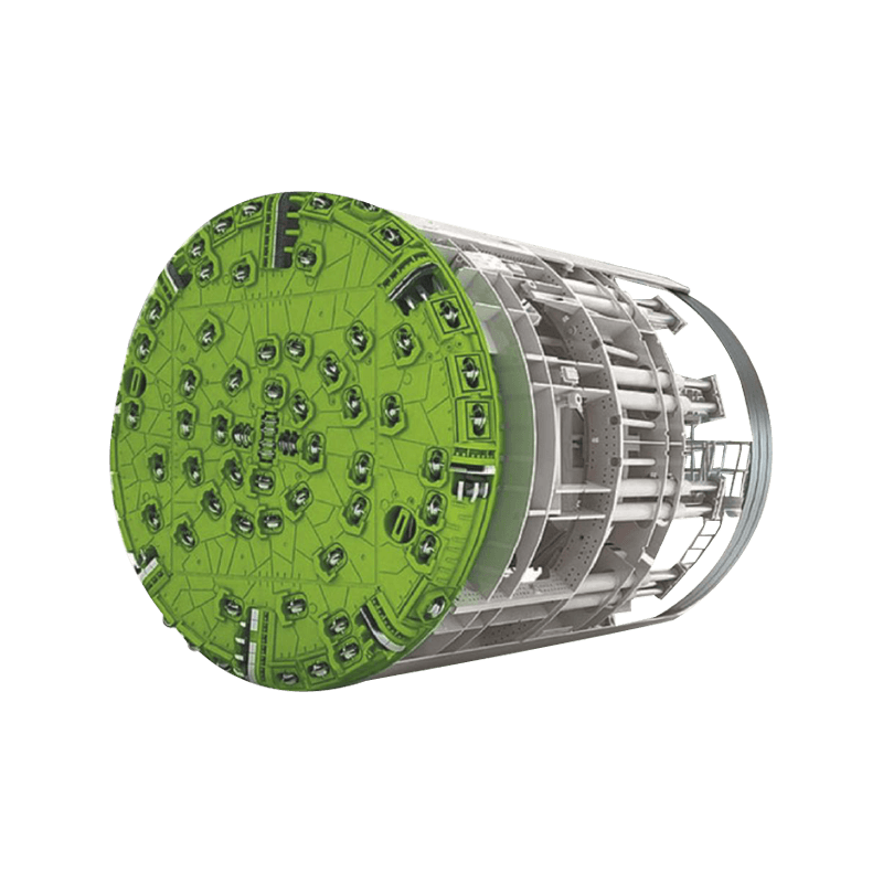
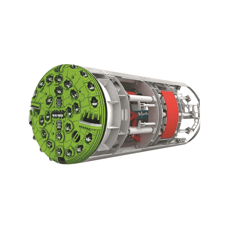
| Earth Pressure Balance (EPB) TBM | 1,200mm – 3,500mm+ | Man-entry | Mixed ground, soft to medium rock |
| Rock Pipe Jacking Machine | 600mm – 2,500mm | Remote or man-entry | Hard rock formations |
| Pilot Tube Microtunnelling System | 100mm – 600mm | Remote-controlled | Soft to medium soils, high accuracy needed |
Slurry Microtunnelling Machines
Slurry pipe jacking machines are the most widely used type globally. They operate entirely by remote control from a surface control cabin, making them safe in confined, pressurised, or contaminated ground conditions. A pressurised slurry circuit maintains face stability, even in water-bearing soils, while carrying excavated material back to the surface for separation and disposal. These machines achieve very high accuracy — typically within ±25mm of design alignment — and are suitable for most urban pipe jacking projects.
Auger Boring Machines
Auger boring machines (ABMs) use a rotating helical screw to convey spoil back through the casing to the launch shaft. They are simpler and cheaper to operate than slurry systems but are limited to dry ground conditions above the water table. ABMs are commonly used for road and railway crossings in stable, cohesive soils such as clay. Steering control is more limited than slurry microtunnelling, so they are less suitable for long drives or where very tight tolerances are required.
Man-Entry Pipe Jacking Machines
For pipe diameters above approximately 1,200mm, man-entry becomes possible and a human operator can work at the cutting face to assist with excavation, obstruction removal, and machine maintenance. Man-entry pipe jacking operations require comprehensive safety measures including atmospheric monitoring, rescue procedures, and compressed air or pressurised face support systems where groundwater is present. These machines are commonly used for large-diameter sewer tunnels, culverts, and utility corridors in major infrastructure projects.
Pipe Materials Used in Pipe Jacking Operations
Not all pipe materials are suitable for jacking. The pipe must be strong enough to transmit the full jacking thrust load along its length without cracking, buckling, or joint failure. The following materials are most commonly used in pipe jacking projects:
- Reinforced Concrete Pipe (RCP): The most widely used jacking pipe material. Specially manufactured jacking-grade RCP has reinforced steel cages, precision-machined end faces, and intermediate packing rings to distribute jacking loads evenly across the joint. Available in diameters from 300mm to 3,000mm+.
- Glass-Reinforced Plastic (GRP) Pipe: Lightweight and highly corrosion-resistant, GRP jacking pipes are increasingly used for sewer and drainage applications. They require careful handling due to their lower compressive strength compared to concrete, but their smooth internal bore provides excellent hydraulic flow characteristics.
- Vitrified Clay Pipe (VCP): Used for smaller-diameter sewer and drainage jacking applications, typically 150mm–600mm. Vitrified clay is highly resistant to chemical attack and abrasion, making it an excellent choice for aggressive sewer environments.
- Steel Pipe: Used for water mains, gas mains, and industrial pipelines where high working pressure is required. Steel jacking pipes are welded or flanged at the joints and require corrosion protection via internal lining and external coating or cathodic protection.
- Ductile Iron Pipe: Occasionally used for pressure pipeline applications in smaller diameters. Ductile iron provides high tensile and compressive strength but is heavier than GRP or concrete alternatives.
Factors That Affect Pipe Jacking Machine Selection
Selecting the right pipe jacking equipment for a specific project involves evaluating a combination of ground conditions, geometric requirements, site constraints, and programme demands. Getting this selection wrong can result in machine stalls, excessive wear, inaccurate installation, or project delays.
Ground Conditions and Soil Classification
Ground investigation data is essential before selecting a pipe jacking machine. The key parameters to assess include soil type (clay, sand, gravel, rock), groundwater level and pressure, unconfined compressive strength (UCS) for rock, presence of boulders or obstructions, and soil permeability. A slurry microtunnelling machine is generally required wherever the water table is above the invert level of the pipe, as face support pressure is needed to prevent ground collapse and water ingress.
Drive Length and Alignment
Drive length directly determines the jacking force required, the need for intermediate jacking stations, and the lubrication strategy. Most standard pipe jacking machines can handle drives up to 100–200 metres from a single launch shaft. Beyond this, intermediate jacking stations and enhanced lubrication programmes are necessary. Curved drives — where the pipeline follows a horizontal or vertical radius — require machines with articulated bodies or flexible shields capable of making steering corrections through the curve without transmitting excessive bending moments to the pipe string.
Accuracy Requirements
Gravity sewer systems require accurate grade control, often within ±10–15mm of the design invert level, to ensure proper self-cleansing flow velocities. Slurry microtunnelling systems with laser or gyroscopic guidance are capable of achieving these tolerances reliably, while auger boring is generally considered acceptable only for crossings where ±50mm or greater tolerance is acceptable. For drives where the exit position must precisely meet a pre-formed opening — such as a manhole chamber or reception pit — high-precision navigation systems are non-negotiable.
Site Constraints and Shaft Locations
The available footprint for launch and reception shaft construction can constrain machine choice. In tight urban locations, space-restricted shaft configurations may limit the use of standard-length jacking frames, requiring purpose-built short-stroke frames or a modular setup. Access for delivery of plant, pipe sections, and slurry separation equipment must also be carefully planned, as these machines generate significant surface infrastructure around the shaft during operation.

Advantages of Using a Pipe Jacking Machine Over Open-Cut Methods
The case for using a pipe jacking machine rather than conventional open-cut trenching is compelling in a wide range of situations. The primary benefits include:
- Minimal surface disruption: Only the launch and reception shaft locations require open excavation. The road, railway, river, or building above the pipe route remains undisturbed throughout the installation, eliminating the need for road closures, traffic diversions, or structural shoring over the pipe route.
- Reduced environmental impact: No spoil is generated along the pipe route — all excavated material comes up through the launch shaft. This reduces the volume of material to be transported and disposed of and avoids ground contamination risks from open trenching through chemically affected soils.
- Lower whole-life cost in congested areas: While the upfront cost of a pipe jacking machine and operation is higher than simple open-cut trenching, the total project cost in urban or trafficked environments is often lower when road reinstatement, traffic management, business disruption claims, and utility diversions are taken into account.
- Installation at greater depths: Pipe jacking allows pipelines to be installed at depths that would be impractical or unsafe with open excavation, without the need for expensive deep-trench shoring systems. This makes it ideal for deep sewer gravity mains and underpasses.
- Stable ground conditions maintained: Slurry and EPB pipe jacking machines apply controlled face pressure to balance the in-situ ground and water pressures, preventing ground settlement above the pipe route — a critical advantage when working under sensitive structures, heritage buildings, or live railway tracks.
Common Challenges in Pipe Jacking Operations and How to Manage Them
Pipe jacking is not without its technical challenges. Experienced contractors and engineers are well aware of the risks that can arise during a drive and have established strategies to manage them effectively.
Obstructions at the Face
Unexpected boulders, buried masonry, timber piles, or other obstructions can halt a pipe jacking drive and cause significant delays and cost overruns. Pre-drive ground investigation, including window sampling, trial pits, and geophysical surveys, is the best way to reduce this risk. When obstructions are encountered mid-drive in man-entry sized machines, they can sometimes be broken up or removed at the face. In smaller diameter microtunnels, intervention is far more complex and may require ground treatment or a compressed air dive to access the face safely.
Excessive Jacking Loads
If lubrication is inadequate or ground conditions are more frictional than anticipated, jacking loads can escalate to levels that risk cracking the pipe string or stalling the main jacking frame. Monitoring jacking force continuously throughout the drive allows the operator to respond early — by injecting additional lubrication, adjusting thrust speed, or activating intermediate jacking stations — before loads reach critical levels. Pipe jacking contractors typically establish a maximum permissible jacking load for each pipe size and material before the drive begins.
Machine Drift and Alignment Errors
Even well-set-up pipe jacking machines can drift off line and grade due to variations in soil resistance across the face, steering overcorrections, or machine wear. Regular monitoring of the navigation system — at minimum after every pipe section is pushed — allows small corrections to be made gradually rather than allowing the deviation to accumulate. Large steering corrections made late in a drive can induce bending stresses in the pipe string and create difficult ground contact conditions that increase jacking loads.
Groundwater Ingress and Face Instability
Working in water-bearing ground without adequate face support can lead to soil washout, surface settlement, or machine flooding. Slurry pipe jacking machines are specifically designed to manage this through pressurised slurry circuits, but any drop in slurry pressure — due to a pump failure, pipe blockage, or incorrect setup — can rapidly destabilise the face. Redundant pumping systems, continuous pressure monitoring, and well-trained operators are essential safeguards in high-risk groundwater conditions.
Typical Applications for Pipe Jacking Machines
Pipe jacking machines are used across a remarkably wide range of infrastructure sectors. The following are among the most common application areas:
- Sewer and drainage installation: Gravity sewer mains, combined sewer overflows (CSOs), and stormwater drainage pipes are routinely installed by pipe jacking in urban areas where open-cut work is not feasible.
- Water supply mains: Pressure water mains crossing roads, rivers, or rail corridors are frequently installed using steel or ductile iron pipe jacking to avoid the disruption and cost of open excavation.
- Road and railway crossings: Pipe jacking is the standard method for installing new pipes, cables, and culverts beneath live highways and railways, where track or road possession costs make open-cut methods commercially unviable.
- River and waterway crossings: Pipelines and utility ducts are jacked beneath rivers, canals, and tidal waterways where horizontal directional drilling (HDD) is not suitable due to soil conditions or diameter requirements.
- Utility ducting and cable protection: Telecommunication, power, and gas utility bundles are increasingly installed in concrete or GRP ducts using microtunnelling pipe jacking to future-proof urban infrastructure corridors.
- Airport and port infrastructure: Airside utility crossings at airports and subsea pipelines at ports are specialist applications where surface disruption must be kept to an absolute minimum, making pipe jacking the only viable installation method.
Cost Factors in a Pipe Jacking Machine Operation
The cost of a pipe jacking operation varies widely depending on ground conditions, pipe diameter, drive length, access constraints, and pipe material. However, understanding the main cost drivers helps project owners and engineers make informed decisions when comparing trenchless options with conventional open-cut methods.
| Cost Component | Typical Share of Total Cost | Key Variables |
| Machine mobilisation and setup | 15–25% | Machine size, site access, shaft construction |
| Pipe supply and delivery | 20–35% | Pipe material, diameter, wall thickness |
| Drive operation (labour, consumables, slurry) | 25–40% | Ground conditions, drive length, advance rate |
| Shaft construction and reinstatement | 10–20% | Depth, groundwater level, shaft type |
| Spoil disposal and slurry treatment | 5–15% | Soil contamination, disposal distance, volume |
As a rough guide, small-diameter microtunnelling pipe jacking in straightforward ground conditions might cost in the range of £1,500–£4,000 per linear metre installed, while large-diameter man-entry pipe jacking in complex urban ground can exceed £10,000–£20,000 per linear metre. These figures include all associated shaft works, pipe supply, and machine operation but exclude design, ground investigation, and project management fees.


